
-
×
 Underground Cable Wire Locator -NOYAFA - NF-816-C
KSh 4,640.00 (incl. tax)
Underground Cable Wire Locator -NOYAFA - NF-816-C
KSh 4,640.00 (incl. tax)
Aico LAN 3in1 Cable Tester
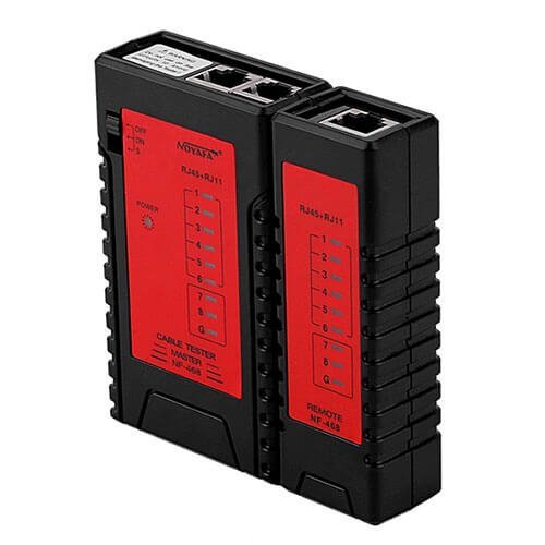
Aico LAN 3in1 Network Cable Tester
Universal LAN tester
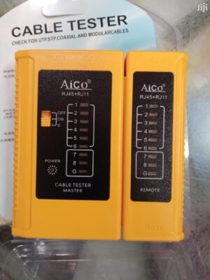
A Network Cable Tester is a tester of network cables with twisted pair, straight and crossover wire configurations. Resolving network connectivity issues is often a mere process of elimination.
Main Function: Verify RJ11, RJ45 cables
Tracking Type : RJ11 & RJ45
Power: 9V Alkaline battery
Following are abnormal connections:
If one cable, for example, cable NO.3 is open-circuited, the two NO.3 lights of the main tester and remote tester will not turn on.
If several cables are not connected, several lights will not turn on respectively. If less than two cables are connected, none of the lights is on.
If two ends of a cable are disordered, for example, NO. 2and NO. 4, then displays on:
Main tester: 1-2-3-4-5-6-7-8-G
Remote tester: 1-4-3-2-5-6-7-8-G
If two cables are short-circuited, neither of the corresponding lights is on of the remote tester while the main tester remains unchanged.
If three cables, including three, are short-circuited, none of the corresponding lights is on.
If test patch panels or wall plate outlets, two cables that can match each other (RJ45) will be connected to the tester.
This network cable tester helps determine whether or not a network cable is the source of the problem. To use, connect one end of the network cable to the “Master” controller and the other end to the “Remote”.
Turn the switch found on the Master controller to the on position to begin testing. If the network cable is working properly, the Master controller and the Remote will illuminate sequentially with green lights.
When testing cables with RJ-11 connectors, lights 1 through 6 should illuminate. When testing cables with RJ-45 connectors, lights 1 through 8 should illuminate.
How to Test Your Ethernet Cables Using a Network Cable Connector.
The device is Super-simple to use!
1) Install a 9V battery
2) Connect your “test” cable to the appropriate jacks on the Main UNit and “Remote” unit
3) Turn it on. The RED “POWER” LED will start blinking: FAST in the “ON” position, SLOW in the “S” position
4) Watch the GREEN LEDs on the Main unit sequence from “1” to “G”, then repeat until you turn the Main unit OFF or disconnect the cable. Place the POWER switch in the “S” (Slow) position to better observe the LED sequencing.
5) The GREEN LEDs on the “Remote” unit will sequence with the Main unit’s LEDs, with the “Remote” LEDs indicating which wires are connected to each other.IDEALLY, one ONE LED on each of the Main and “Remote” units will light in sequence. If NO LED on the “Remote” unit lights for a given Main unit LED, that wire IS NOT CONNECTED between the two points. READ THE INCLUDED DIRECTION SHEET to interpret other “LED ‘patterns, etc.’”
Also check out Universal 3in 1 Cable Testers
Be the first to review “Aico LAN 3in1 Cable Tester”
FLASH DEALS
LIVE NOW
Ends In:
04
h
:
40
m
:
54
s
-
 Epson EcoTank L14150 A3+ Wi-Fi Duplex Wide-Format All-in-One Ink Tank Printer
Original price was: KSh 120,000.00.KSh 105,000.00Current price is: KSh 105,000.00. Ex.VAT
Epson EcoTank L14150 A3+ Wi-Fi Duplex Wide-Format All-in-One Ink Tank Printer
Original price was: KSh 120,000.00.KSh 105,000.00Current price is: KSh 105,000.00. Ex.VAT -
 Panasonic KX-TS7703X Phone .Landline Analog Phone
KSh 3,200.00 Ex.VAT
Panasonic KX-TS7703X Phone .Landline Analog Phone
KSh 3,200.00 Ex.VAT -
 Canon I-SENSYS MF651Cw A4 Colour Multifunction Laser Printer
Original price was: KSh 57,500.00.KSh 49,800.00Current price is: KSh 49,800.00. Ex.VAT
Canon I-SENSYS MF651Cw A4 Colour Multifunction Laser Printer
Original price was: KSh 57,500.00.KSh 49,800.00Current price is: KSh 49,800.00. Ex.VAT -
 Epson T6732 Cyan Ink Cartridge - 70ml
KSh 2,650.00 Ex.VAT
Epson T6732 Cyan Ink Cartridge - 70ml
KSh 2,650.00 Ex.VAT -
 HP LaserJet Pro 4003dn Printer
Original price was: KSh 49,000.00.KSh 46,000.00Current price is: KSh 46,000.00. Ex.VAT
HP LaserJet Pro 4003dn Printer
Original price was: KSh 49,000.00.KSh 46,000.00Current price is: KSh 46,000.00. Ex.VAT
Related products
Sale!

Tools & Accessories
Heavy Duty RJ45 Crimp Tool for Rj 11 4p, RJ12 (6P) and RJ45 (8P)
Original price was: KSh 3,800.00.KSh 2,100.00Current price is: KSh 2,100.00. Ex.VAT

Sale!

Tools & Accessories
Original price was: KSh 2,000.00.KSh 1,500.00Current price is: KSh 1,500.00. Ex.VAT

Sale!


Networking Equipment
Original price was: KSh 16,500.00.KSh 16,000.00Current price is: KSh 16,000.00. Ex.VAT

Sale!

Tools & Accessories
Original price was: KSh 1,100.00.KSh 950.00Current price is: KSh 950.00. Ex.VAT

Expert Shopping Guides, Product Reviews & Top Recommendations
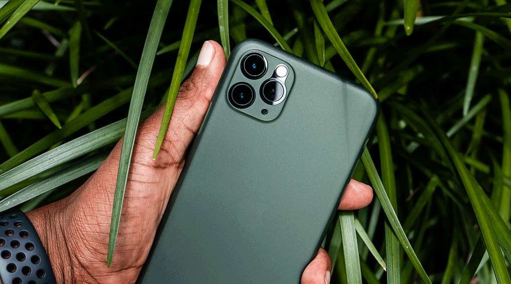
What Is a Smartphone? A Mobile Phone and Computer In One Device
Lorem ipsum dolor sit amet, consectetur adipiscing elit. Quisque pretium mollis ex, vel interdum augue [...]
4 Comments
27
Feb
Feb

Can the Apple Watch Series 7 Work On Its Own Without an iPhone?
Lorem ipsum dolor sit amet, consectetur adipiscing elit. Quisque pretium mollis ex, vel interdum augue [...]
26
Feb
Feb
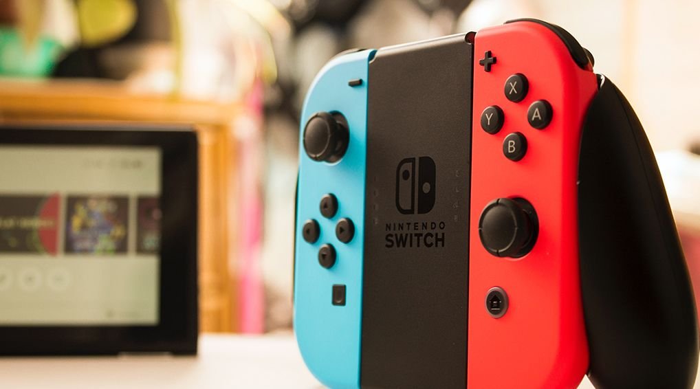
Bluetooth gamepad for Windows and Android
Lorem ipsum dolor sit amet, consectetur adipiscing elit. Quisque pretium mollis ex, vel interdum augue [...]
25
Feb
Feb
Quote
It's estimated that more than 5 billion people have mobile devices, which represents approximately 94% [...]

New or Refurbished Computer? It’s a Matter of Dollars and Sense
Lorem ipsum dolor sit amet, consectetur adipiscing elit. Quisque pretium mollis ex, vel interdum augue [...]
22
Feb
Feb

Apple Watch Adds Carbon Neutral Options & Spec Upgrades
Lorem ipsum dolor sit amet, consectetur adipiscing elit. Quisque pretium mollis ex, vel interdum augue [...]
21
Feb
Feb

Headphone Beze Emgyrean II Review
Lorem ipsum dolor sit amet, consectetur adipiscing elit. Quisque pretium mollis ex, vel interdum augue [...]
20
Feb
Feb
Reviews
There are no reviews yet.